Dimensional reference planes, causes of dimensional changes and moulded part acceptance conditions
The dimensional variation in the application and production of plastic moulded parts requires the consideration of three closely connected dimensional reference planes: Parts application, parts production, tool production. For the dimensional reference planes, different physical causality relationships must be observed and systematically merged, whereby the design of the construction is to be processed mentally in the opposite direction to the direction of dimension formation. The principle of different dimensional reference planes is also clearly explained in DIN 16742 (Annex A).
Figure 1 shows the dimensional quantities and dimension relationships with respect to position (center of tolerance dimension C), displacement (offset Δl), and dispersion (tolerance T) for the dimensional reference planes. The direction of the dimensional displacement is taken into account by sign.
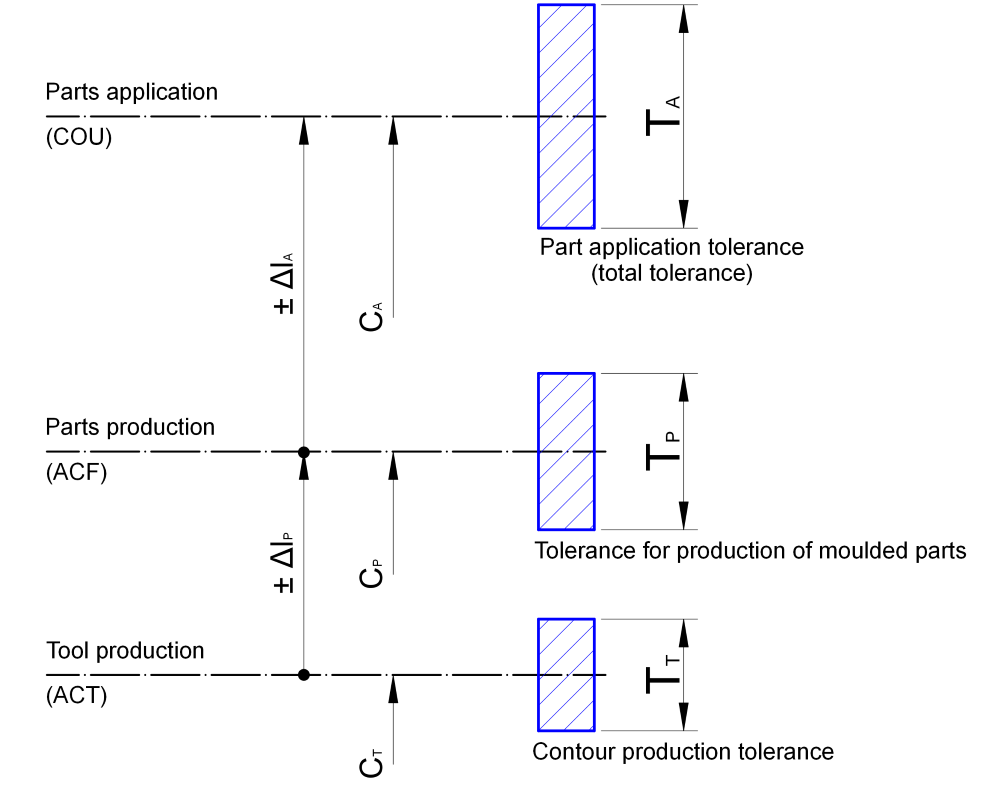
Figure 1: Dimensional reference planes for application and production of plastic parts
Conditions of use (COU): All conditions of use and storage of the parts during the period of use after manufacture, provided that they affect the dimensional accuracy and functional performance of the products.
If assembly or completion of the individual parts to form assemblies only takes place in longer periods after the parts have been manufactured, the parts storage and completion conditions may have to be treated as a special case by the COU. For soft or rubbery moulding materials, the influence of the COU can often be neglected. The same applies to assemblies made of completely identical materials. In each individual case, however, the COU must be determined depending on the situation and function. For the part user, the recording of the company-specific COU and its influence on dimensional accuracy is a useful rationalization tool. A general compilation or standardization of all COU is not possible due to the large number and complexity of the influences.
Cause factors of the application-related dimensional change (all relevant factors are summarised in groups below):
- Climate effects due to ambient temperatures, humidity, precipitation and solar radiation,
- Energy effects caused by heat sources and high-energy radiation,
- Diffusion contact with vapours and liquids as well as migration contact with solids,
- Material removal (wear) due to friction, cavitation and erosion as well as biological influences,
- Mechanical deformation by external forces and moments as well as by relaxation of internal stresses,
- Molecular and micromorphological material structure transformations.
Causes for length deviations due to production:
- Scattering of processing shrinkage depending on moulding compound and production,
- Uncertainties in the determination of calculated values of the processing shrinkage for tool contour calculation, especially with large shrinkage values and with shrinkage anisotropy,
- Different reshaping behaviour of the parts after demoulding, depending on the stiffness or hardness of the moulding material,
- Production-related dimensional variation of the tool contours including hardness distortion and surface coating,
- Deformations and positional deviations of tool parts due to compressive stress,
- Tool contour wear.
Causes of moulding distortion: Distortion (warping, twisting, warping) is the physical cause of deviations in shape, position and angle of the plastic moulded parts. It is caused by local and direction-dependent shrinkage differences (shrinkage anisotropy) and at extreme post- or compression pressure by re-deformation (relaxation) of elastic residual stresses. In principle, distortion of molded parts cannot be avoided, but can be minimized (Chapter 5).
Acceptance conditions for the production of fittings (ACF): For normative acceptance conditions according to ISO 20457/DIN 16742 and DIN EN ISO 219, the test dimensions are considered acceptance values if the fittings are stored at 23 °C ± 2 K and 50 % ± 10 % relative humidity after production until acceptance and are tested at the earliest 16 h and at the latest 72 h after manufacture.
In case of deviations from the normative ACF, the acceptance parameters for the control dimension test according to ISO 20457/DIN 16742 must be agreed and documented separately between manufacturer and customer:
- Dimensional position and deviations (if necessary after testing),
- Dimensional inspection procedures,
- Minimum and maximum period of dimensional inspection after parts production,
- Storage and test conditions until parts are removed (room air temperature, relative air humidity, special storage regulations if necessary).
Deviations from the normative ACF can be:
- Subsequent operations at the parts manufacturer with material application (painting, coating) or material removal (machining, grinding, polishing),
- Post-treatment of parts by tempering (anticipation of post-shrinkage, compensation of internal stresses, post-hardening) or subsequent operations with significant thermal stress on parts (painting, solder bath treatment, etc.)
- Partial after-treatment by conditioning, e.g. by watering (anticipation of swelling, increase in toughness),
- Low dimensional stability of the structure and condition of the moulding material at ACF. Examples are structural changes in the crystalline phase of semi-crystalline polymers (e.g. PB) and swelling as well as softening due to water absorption of thin-walled molded parts made of hydrophilic polymers (e.g. PA6, PA66, PA46, biopolymers).
Acceptance conditions for tool production (ACT): The control dimensions of the tool contours determined by testing are considered acceptance values at a reference temperature of 23 °C ± 2 K. They include hardening distortion.