Notes
Injection molded parts are characterized by a wide range of geometric design variety and complexity. The software offers a wide range of options for describing the many geometric elements ( molded part sections) of a molded part. Therefore, the user has the task to divide his concrete molded part into such sub-parts with sufficient precision.
The part with the longest cooling time is then decisive for the cycle.
SPRUE GEOMETRY DETERMINING COOLING TIME
- In injection molding with a fixing sprue, in unfavorable (but usually avoidable) cases the sprue manifold cross-sections can be cooling time-determining and can be traced back to the specified manifold shapes.
- In the case of branched sprue systems, the largest cross-section should be selected in each case for the same cross-section shape.
COOLING TIME-DETERMINING MOLDING GEOMETRY
- The cooling time determining molding section shall be determined by selecting applicable geometry elements or their combination as well as by creative approximation assignments.
- All prismatic or profile-like sections can be straight or curved in the lengthwise direction. In the case of cross-sectional dimensions that vary in sections, the maximum values are usually the ones that determine the cooling time.
- Cross-section increases due to radius transitions between part sections can be taken into account by increasing the wall thickness input by approx. 25 % for adjacent flat part elements.
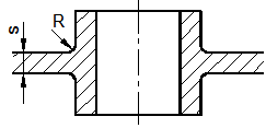
Example: Input: (s · 1.25) mm